|
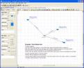
View Example 01: Flow between Three Reservoirs
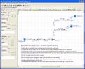
This is a classic example that is found in most text books. Three reservoirs are each located at different elevations and are joined at a common point by three pipes.
|

|
View Example 02: OutFlow from a Tank along a pipe
This demonstrates flow from a tank through a single pipe that has a set demand flow at its end point.
|
|
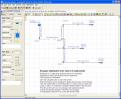
View Example 03: Flow from a Tank to Three Outlet Points
In this example the discharge is to 3 outlet spray positions. Each spray nozzle requires a 2.3 psig pressure to produce the correct spray pattern. |
|
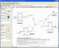
View Example 04: Pumping fluid to Three Tanks
Fluid is to be transferred from a tank at low level to 3 tanks located at a higher level. A pump is needed as the motive force to provide the energy to move the fluid.
|
|
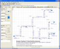
View Example 05: Fixed Head Pumping to Three Tanks
The flow rate along all paths has been specified. The problem is to determine the pump head needed to deliver the total flow. A fixed head pump is used to add pressure to the model. An initial added pressure of 20 ft head of water has been chosen as a possible solution.
|
|
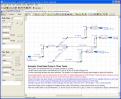
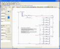
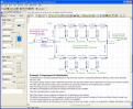
View Example 06: Fixed Speed Pumping Chemical Transfer System
This system design includes a stainless steel pump used to transfer a chemical to two tanks at a set flow rate to each tank. The flow to each tank is regulated by a flow control valve set to limit the flow rate. The system includes a special filter which has been modeled by adding a Component to pipe P3.
|
|
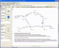
View Example 07: Flow from Pressurized Pumping Stations
This example demonstrates the power and flexibility of the Pipe Flow Expert software. Some pipes and pumps have been temporarily removed from the system, leaving isolated legs where flow will not occur. Pipe Flow Expert is able to identify this situation and find a solution for the remainder of the pipe network.
|
|
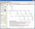
View Example 08: Flow in a Water Circulation System
This system demonstrates a recirculation design where some of the fluid is returned to the start point to be circulated again and some of the fluid is removed. The fluid to be removed is specified by setting a Demand Out-flow from the system at various nodes.
|
|
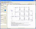
View Example 09: Cooling System, 12 Air Handling Units
This system provides cooling water to the cooling coils of 12 AHU’s located on 3 floors of a building. The cooling tower is located at the roof level.
|
|
View Example 10: Compressed Air Distribution
This example shows a compressed air system where the air is distributed around a 'ring main loop' system to maximize distribution efficiency when some demands are not in use.
|
|
View Example 11: HVAC System (heating, ventilation and air conditioning)
In this example, the heating, ventilating and air-conditioning system to three floors is provided via ceiling mounted fan coil units. The cooling circuit contains a separate pump to supply each floor.
|
|
View Example 12: Reverse Pipe direction where calculated flow is negative
A water distribution system has been designed to deliver a different set flow rate to each of 4 take-off points. During the drawing of the system, Pipe 2 has been added assuming a flow direction that is not correct. This example shows how Pipe Flow Expert recognizes this and reverses the incorrect flow direction.
|
|
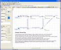
View Example 13: Energy Recovery with Turbine System
This water distribution system incorporates two pumps to raise water to higher elevations. A turbine has been designed into the system to recover some of the energy used in the water distribution.
|
|
View Example 14: Top up Tanks with Pressurized Recirculation System
Three similar views of a domestic heating system are shown. All layouts are fully recirculating with no flow outlets from the system. A top-up tank is incorporated into the designs to make up any leakage from the system.
|
|
View Example 15: Replacement Pipe Size
Water is being transferred from an upper reservoir to a reservoir at a lower level using the difference in head between the surface elevations as the motive force. It is proposed to replace the leaking system with new PVC (AWWA) pipe.
|
|
View Example 16: Step by Step Walkthrough Example
Pipe Flow Expert will allow prospective users to create small systems which can contain up to 5 pipes when the software is in trial mode. The Pipe Flow Expert help file contains detailed step-by-step instructions for each action needed, to create and solve this example system.
|