|
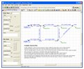
Pipe Flow System Drawing Area
Design, build, view and edit your system model with Pipe Flow Expert's powerful and easy to use interface. The drawing area will let you define tanks, pipes, fittings, valves, pumps, components, flow controls and demands.
|

|
Configure Pipe Flow Units
Choose the units that you want to work in for each field type. The units can all be set to metric or imperial on mass, or can be configured on an item by item basis as required.
|

|
Configure Pipe Flow Labels
Choose the labels that you want displayed on the drawing in design mode and the labels that you want displayed on the drawing in results mode.
|

|
Fluid Database and Fluid Characteristics
Choose fluid data from our database of common fluids. New fluid entries can also be created by the user and stored in the database.
|

|
Pipe Size & Materials Database
Choose from a database of standard pipe materials and standard pipe sizes for that material. New pipe material and size data can be added to the database as required.
|

|
Pipe Fittings Database
Choose from our database of fittings information to add fitting information onto pipes. New fittings data can be created by the user and stored in the fittings database.
|

|
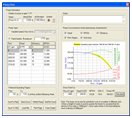
Pump Characteristics & Curve Data
Define a pump as a curve of flow versus head produced or as a fixed flow rate pump. Pumps can be saved and loaded independently to make it easy to copy and duplicate pumps as required.
|

|
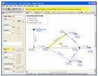
Pipe Flow Expert Results shown in Drawing Pane
When the system is solved the chosen results labels are shown on the drawing, such that the flow or velocity of fluid in each pipe can be seen. In results mode, you can hover over an item to display its results. For example hovering over a pump, shows the pump head produced, the NPSHa available, etc.
|

|
Results Grid
The results grid shows a spreadsheet table of results for pipes, nodes, pumps, fittings, and overall system data. The data in the grid can be also exported to an excel spreadsheet with just one mouse click.
|