Pipe Flow Expert - Software Design Details, Analyzing Pipe Networks

Flow of fluids through a pipe network may be as simple as a single pipe carrying water from one reservoir to another reservoir, or it may be very complex with many interconnected pipes that distribute the flow of fluid throughout a large pipe network with loops and various discharge tanks.
Our Pipe Flow Expert software can model pipe networks and calculate the flow and pressure throughout a system with different pipe sizes and pipe materials, supply and discharge tanks, looped-systems, pumps, valves, flow controls, system demands, heat exchangers and other component.
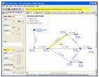
The pipeline system is modeled by drawing the join points and the connecting pipes on a drawing pane. Horizontal, vertical or sloping lines can be used to connect one node to another node.
 The physical data describing the system is entered by the user and typically includes:
- The internal size, internal roughness and length of each pipe.
- The elevation of each pipe join point (node).
- The In-flow and the Out-flow at each join point (if applicable).
- The elevation, liquid level and surface pressure data for each tank.
- The performance data for each pump (the pump characteristic curve).
Data input boxes are located at the left hand side of the drawing pane. These input boxes will display the data for the currently selected node or pipe and may be used to amend the current data. The data for a node, pipe, component, pump, etc. can be amended at any point during the design (drawing) process.
Once the design has been completed, the system can be analyzed and the flow and pressure results can be calculated. Estimates for the out-flows are used to set an initial flow rate in each pipe, with the total in-flow to each join point matching the total out-flow from each join point. The pressure losses within the system are calculated using friction factors obtained from the Colebrook-White equation, and the friction pressure loss for each pipe is obtained from the Darcy-Weisbach equation.
The initial flow estimates are unlikely to give a balanced pressure result over the whole system and must be further refined using an iterative approach to adjust the flow rates until a pressure balance is achieved. Pipe Flow Expert defines the elements of the pipeline system in a series of matrix equations and uses the Newton method to adjust the initial estimates for the flow rate in each pipe. Once an approximate solution has been obtained, the results are refined using a variation of the Newton method to ensure convergence until a balanced pressure result is obtained.
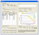 The results of the flow rates for each pipe, the fluid velocities for each pipe, Reynolds numbers, friction factors, friction pressure losses for each pipe, fittings pressure losses, pressure at join points (nodes), HGL (hydraulic grade line), pump operating points and more can be viewed on the drawing and on the results grid.
|