|
|
|
|
Pipe Flow 3D - Checking if you can pump the fluid?
Will the pressure on the fluid surface & the effect of any
positive or negative fluid head be sufficient to ensure that the full flow rate
required will reach the pump inlet?
Will the lowest fluid pressure,
which occurs in the pump inlet, fall below the fluid vapour pressure, and hence
cause cavitation to occur?
You will needs to establish the inlet condition to the
pump
and establish the discharge pressure that the pump must
overcome.
Getting Fluid to the Pump?
|

[ Now superseded by
Pipe Flow Expert ]
|
What about pump suction? Pumps do not
suck!
It is a common belief that pumps provide the energy to lift
fluid to the pump inlet. This is not true.
The pump simply moves
fluid from the immediate inlet pipework and discharges this fluid against the
outlet pressure in the discharge system. This action creates a local suction
effect, which allows the external forces acting on the fluid intake system to
push the remaining fluid in the intake system towards the pump inlet. This
alternative (actual) view of what is happening within the pipework system
leading to the pump inlet will help in understanding the limitations introduced
by bad pipework system design.
If the inlet system arrangement does not
provide enough energy to move the required flow rate to the pump inlet, the
pump will be starved of fluid and the required flow rate will not be delivered.
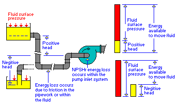 Getting fluid to the pump Getting fluid to the pump
The air pressure on the fluid surface is the usual energy source used
to push the fluid into the pump.
A supply container positioned above the
pump inlet will increase the available energy.
A supply container
positioned below the pump inlet will reduce the available
energy.
Resistance to fluid flow
Fluids in
motion are subjected to various resistances, which are due to friction.
Friction may occur between the fluid & the pipe work, but friction also
occurs within the fluid as sliding between adjacent layers of fluid takes
place. The friction within the fluid is due to the fluid’s viscosity.
When fluids have a high viscosity, the speed of flow tends to be low,
and resistance to flow becomes almost totally dependant on the viscosity of the
fluid. This condition is known as ‘Laminar flow’.
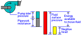 Will the required flow
rate actually reach the pump inlet? Will the required flow
rate actually reach the pump inlet?
The energy losses in the
pipework system must be calculated. This energy loss must be subtracted from
the available energy to obtain the condition at the entrance to a pump.
The inlet condition is commonly referred to as the ‘suction
condition’ - Leading to the idea that pumps suck.
If the theoretical pump inlet pressure is too low the system
will operate at some lower flow rate or the pump may not operate at
all.
Boiling fluid (Cavitation)
Many fluids
will boil at ambient temperature if the pressure is reduced below a particular
level. This pressure is referred to as the ‘Vapour pressure’ of the
fluid.
If the pump inlet pressure falls below the vapour pressure of
the fluid, gas bubbles will form in the fluid. These bubbles will be moved
through the pump. The bubbles will collapse when the fluid pressure is raised
on the discharge side of the pump. The effect of this is to reduce the flow of
delivered fluid. In some systems the effect can cause dramatic vibrations, and
may result in damage to the system and the pump.
Increasing the
pressure at the pump inlet
Small pipe sizes will result in high
pipework energy losses. Increasing the pipework size will help to reduce this
energy loss.
In the case of high viscosity fluids, increasing the
pipework size may not have the desired result. Also, commercial considerations
may limit the size of the pipe that can be used.
 Under these circumstances, the easiest solution is to raise the
position of the supply container, to increase the positive head available, thus
more force will be available to push the fluid through the pipework. Under these circumstances, the easiest solution is to raise the
position of the supply container, to increase the positive head available, thus
more force will be available to push the fluid through the pipework.
If is not practical to raise the supply container, it may be
necessary to enclose the supply and introduce some positive pressure above
atmospheric onto the fluid surface.
Look out for sealed supply
containers where the force moving the fluid will reduce as the container is
emptied.
Suction units
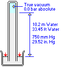 Suction conditions can be described in many different ways. Suction conditions can be described in many different ways.
Normal atmospheric pressure (about 1000 mBar, 14.5 psi.g) will support
a water column of 10.2 metres (33.45 ft) high.
If the fluid column was
Mercury the column height would be 750 mm (29.52 inches) |
Net Positive Suction Head
Check
Pump inlet loss N.P.S.H.r
An energy loss
occurs during fluid entry into most pumps.
This loss is described as
N.P.S.H.r (Net Positive Suction Head requirement).
The N.P.S.H.r is
determined by the pump manufacturer.
The N.P.S.H.r is usually plotted on
pump performance curves.
The N.P.S.H.r is expressed in metres head ( or ft
head) of fluid.
The value of N.P.S.H.r will be dependent on many
factors including flow rate, Impellor design, inlet type, pump speed
etc.
Boiling fluid (Cavitation) (repeated from last
section)
Many fluids will boil at ambient temperature if the pressure is
reduced below a particular level. This pressure is referred to as the
‘Vapour pressure’ of the fluid.
If the pump inlet pressure
falls below the vapour pressure of the fluid, gas bubbles will form in the
fluid. These bubbles will be moved through the pump. The bubbles will collapse
when the fluid pressure is raised on the discharge side of the pump. The effect
of this is to reduce the flow of delivered fluid. In some systems the effect
can cause dramatic vibrations, and may result in damage to the system and the
pump.
Minimum pressure at the pump inlet and N.P.S.H.a
The minimum pressure at the pump inlet minus the ‘Vapour
pressure’ of the fluid is usually known as the Net Positive Suction Head
available (N.P.S.H.a)
This must not be confused
with the N.P.S.H.r published by the pump manufacturer.
Net
Positive Suction Head Check
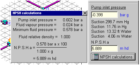 The NPSH calculations featured in Pipe Flow 3D will
display the N.P.S.H.a The NPSH calculations featured in Pipe Flow 3D will
display the N.P.S.H.a
The example graphic here shows how the
calculation is performed.
The N.P.S.H.a must be greater than the pump
manufacturer’s N.P.S.H.r to avoid the fluid pressure falling below the
point at which ‘Boiling of the fluid’ will occur.
|
Use Pipe Flow 3D to carry out your
calculations
Download PipeFlow 3D for a
FREE trial!
|
|
|